The dream phone is a device that enables communication between a lucid dreamer and the outside world.
This dream phone uses EOG (electrooculography) to allow the lucid dreamer to communicate. EOG, like EKG or EEG, reads electric signals from the body. Instead of reading heart beats like EKG, EOG reads eye movement.
The dream phone when I'm wearing it while awake.
When a sleeping person is in a dreaming REM state, they are paralyzed except for the ability to control small twitches, the breath, and eye movements. They can signal with their eyes in morse code and EOG can detect these signals. The dream phone software can then translate the morse code into english letters.
The dream phone in a pile on my desk
Future versions will send messages to the internet. But this version saves messages to a file.
uses file: dream_phone_SD_card.ino
The Dream Phone SD
- Detects rem
- Induces lucidity (through light flashes)
- Translates morse code messages
- Saves messages to a text file on an SD card
- Heart and Brain SpikerShield Bundle
- Arduino Uno
- Breadboard
- 9 volt battery and snap connector
- 1 meter/60 led of LED SMD strip
- Mosfet
- 10k ohm resistor (brown-black-orange)
For this version, we need to hook up the Heart and Brain SpikerShield with wires to the arduino uno, instead of stacking it on top of the arduino. This is because the HB shield will block pins we need for the sd card if we stack it.
Connect the following pins of arduino uno to the same spot on the HB shield if you were to stack it:
D4, D6, D7, GND, 5V, and all the analog pins (A0, A1, etc) though, I'm not sure if all the A's have to be connected.
- Card
CSto ArduinoD5 - Card
MOSIto ArduinoD11 - Card
SCKto ArduinoD13 - Card
MISOto ArduinoD12 - Card
3Vto Arduino3V - Card
GNDto ArduinoGND
Connect the battery snap lines to the long terminals on the breadboard and to then to the arduino:
- Battery Power to Arduino
VIN - Battery Ground to Arduino
GND
-
Cut the led strip to 60 lights. I used an RGB led strip, non-addressable. But this project only uses the reds. On my strip a meter was 60 LEDs.
-
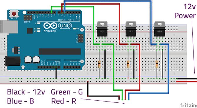
Following this image but only for the red LEDs, connect the red line of the LED strip to the arduino and the mosfet as seen here. Instead of connecting it to
D6as pictures, connect it toD9. In our circuit, the 12V power is actual the 9V battery.-
Connect Arduino pin 9 to the gate leg of the MOSFET, and connect a 10k resistor in line to the ground rail.
-
Connect the Source leg to the ground rail.
-
Connect the Drain leg to the red connector on the LED strip.
-
Connect the power rail (our 9V battery power) to the +12v connector of the LED strip (note that in this image the power wire is black to match the colors of the connectors on most LED strips).
-
Connect the Arduino ground to the ground rail.
-
Connect your 9v power supply to the power rails.
-
That's it for now, in the future I will add how to wear it, set it up, and test it out.


