2x3 Keypad kit
This kit requires SMD soldering of 0805 components and a QFP microcontroller. See this for quick guide in hand-soldering SMD components Recommended soldering order:
- Diodes
- Resistors/Capacitors
- Pushbutton
- Microcontroller
- USB-C
- Crystal
- Switches/Encoder (Test and flash before soldering!)
Diodes have to be soldered in correct orientation. White line facing downwards.
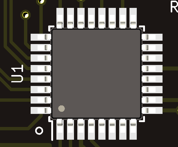
Dot on microcontroller should align with white dot on PCB.
Rest of the components can be soldered in arbitrary orientation.
The keypad can be tested and flashed after soldering the crystal.
- Plug in to computer
- Check device manager for ATmega32u2
- Keypad is working and ready for flashing if ATmega32u2 is detected
- Proceed to flashing
- Download and open QMK Toolbox
- Select the provided .HEX file
- Choose ATMega32u2 as microcontroller
- Push reset button on board and then press flash button in toolbox
Keypad should be flashed and ready to test. Use a jumper wire or tweezers to short the switch pins. The keypad should print numbers 1 to 6.
If flashing does not work, try using v0.0.21 of QMK toolbox
You can now solder the switches/encoder. Encoder is optional and can only be soldered in either top corner (ONLY ONE).
- Download and install VIA Configurator (select .exe for windows)
- Open VIA and go to File->Import Keymap
- Select the file via.json
- Plug in the keypad
The keybinds can now be configured.
This is a common problem. Plug in the keyboard and open the device manager. The keyboard should show up as ATmega32U2, if it instead shows up as unknown device, something is wrong. Follow these steps:
- Check that the USB-C connector has no shorts and all pads are connected. It can be good to retouch the connection even if no obvious problem can be found.
- Do the same thing for the microcontroller chip.
- Also check that the resistors are soldered properly.
- Check the rest of the components.

