Operating Procedure
Much of the operation is intended to be straight-forward, but this is where you can find the details of how to use the system. Just because I intended it to be straight-forward doesn't mean it is, so if you have any questions feel free to ask them on the Discussions tab or on the Discord.
- Mode Selection
- Alarm Panel
- "Hazard" Button Controls
- Manual Operation
- Automatic Process Control Operation
The auto mode selection defines how you will use the system. "Manual" mode puts the reactor into independent, manual operation. This allows use of the START button and allows manual control of the burn rate.

Any mode besides "Manual" locks out use of the START button and burn rate control.
After "Manual" mode, there are four options that all put the unit under control of the automatic process control system. These four options define what priority group this unit resides in.
- Primary - used first
- Secondary - used second
- Tertiary - used third
- Backup - used last (Quaternary was too long of a word to fit)
The system tries to only use the highest priority reactors, but if those have insufficient available burn rate capacity, then it starts using the next lower priority group. Within one group, burn rates are split evenly among reactors in that same group.
Here we'll use an example facility with four reactors with the following burn rate limits: #1 = 250, #2 = 150, #3 = 180, #4 = 350
Units #1 and #2 are set to Primary, unit #3 as Secondary, and unit #4 could be either Tertiary or Backup, it won't matter for this example.
If the system wants a burn rate of 150, then units #1 and #2 both get assigned 75. If it wants 300, then units #1 and #2 both get assigned 150. For 350, units #1 and #2 get assigned 200 and 150 respectively.
At 450, then units #1 and #2 are both running at their limits and the remaining 50 gets assigned to unit #3. After that hits its limit at 580, additional allocation would go to unit #4.
The Prio. Group shows the acknowledged, current control group that the unit is in. The actual mode selection radio options don't reflect the current state, just which was last pressed by the operator, which is why this text indicator is included.
For automatic mode, there is a Ready indicator indicating if the unit is ready for automatic control. This requires that the RPS is not tripped and that all build and status data has been received from the reactor and all the boilers and turbines that are configured for that unit. No RTUs can be faulted (or the PLC, but that's an RPS trip) and all multiblocks must be formed.
The Standby indicator indicates that the reactor is part of automatic control that is currently running, but the reactor is currently disabled due to not being needed at that moment in time. While in standby, this indicator will blink 1 second on 1 second off.

This panel displays and allows acknowledging or resetting the reactor unit alarms. For more details, see the alarms page.
Both the unit view and facility view have an ACK button that will acknowledge all alarms for the unit or facility respectively. While in manual operation, no actions will be taken automatically based on alarms. While in auto mode, high priority alarms will cause an automatic RPS trip (SCRAM) of that reactor unit.
The buttons with "hazard" borders behave in a special way. When disabled, they are grayed out, and when enabled, they have an accent color. Once pressed (while enabled), the text will turn the accent color while the request has been sent but not replied to by the supervisor. Once the reply is received, the text will return to the normal color. If the request times out, it will be on for a bit then blink once then go off. If the request fails, it will blink twice before turning back off.
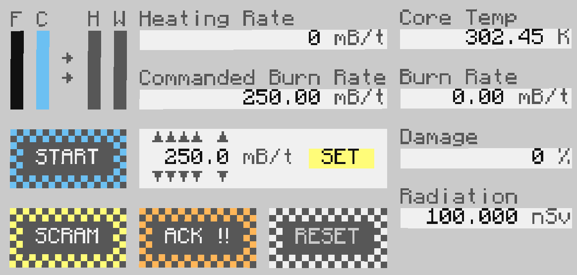
There are 4 main button controls in addition to the burn rate spinbox control. This allows for basic "on/off" functionality, with the ability to set the burn rate before and during operation. Note that the operator has the ability to provide a rate with 1/10ths of decimal precision, but the automatic control utilizes 1/100ths of decimal precision.
Manual operation still has one safety in place, in addition to RPS SCRAMs. This is that emergency coolant is automatically opened if the RPS trips on no (coolant level low low) coolant. Emergency coolant won't be closed again until the RPS is RESET.

While the reactor auto control mode is set to "Manual", the burn rate can be changed via the up/down arrows. The rate is not set until the SET button is pressed. If this succeeds, you will see the "Commanded Burn Rate" show the new rate. If the reactor is active, the "Burn Rate" should also show this rate. This input is limited to the maximum burn rate of the reactor, with a minimum of 0.1mB/t.
Reactor is ready to start
The RPS is tripped via either manual SCRAM with the SCRAM button or a detected safety issue. Before starting, the RPS needs to be reset using the red RESET button. If the hazard condition is still present, it will trip again. While it is tripped, the START button will be disabled. Once everything is all set and the reactor auto control mode is set to "Manual", then the START button will be enabled, turning blue. Once started, that button will again be disabled.

Reactor has been started
To stop the reactor manually, press the SCRAM button. This will trip the RPS, stopping reactor operation. The "Manual Reactor SCRAM" indicator will light up on the reactor annunciator panel.

Reactor has been SCRAM'd
Automatic process control provides various modes to autonomously control your reactor(s). On top of the utility that provides, safety checks are performed both on a facility level and on a unit level to address higher priority alarms and negative facility conditions (high induction matrix charge, for example).
The first part of this is determining the capabilities of all reactors. By default, all the reactors have a limit of their max burn rate. This can be lowered on a per-reactor basis to a limit of the operator's choosing. These settings (and the other control settings) are saved with the SAVE button or by starting auto control mode.
The control mode, limits, and assignment states of reactor units cannot be changed while automatic control mode is active.

For details on this interface, refer to its documentation.
When using monitored max burn and combined max burn, burn rate setpoints are ramped on reactors with non-zero allocations. Ramping brings the reactor up to the commanded burn rate by increasing the commanded rate by 5.0 mB/s. This same ramping is used at the start of generation rate control mode in order to bring the system up to the estimated target based on calculations using the number of turbine blades (this becomes the feed-forward of that control loop).
For details on the different status messages in auto control mode, check out the list.
Monitored max burn is the simplest of the four modes. This mainly provides the benefit of applying all the automatic SCRAM safety checks while running the reactors as simple as possible. Ramping is performed to bring the reactors up to their configured limit, then they are left running full at that limit. If a reactor is lost (SCRAMs, disconnects, etc) then is RESET (after reconnecting if applicable), it will perform ramping again to bring it up to its limit.
Combined burn rate distributes a desired aggregate burn rate across the units assigned to auto control, following the rules of priority order. Ramping is performed to bring reactors to the allocated setpoints. If a reactor is lost, other reactors will attempt to be used to meet the set combined burn rate. If higher priority reactors are restored, then the load is relieved from the lower priority reactors and assigned to the restored reactor(s), and applied via ramping.
Charge level mode attempts to maintain a level of charge in the induction matrix by varying the combined burn rate of assigned reactors. This utilizes a PD controller, covered in more detail by the page on the closed loop controllers. No explicit ramping is performed in this mode; the slow rate change is instead handled by the gains of the control loop.
Generation rate mode attempts to produce a set amount of MFE/t from the assigned reactors. The first stage of this control loop is ramping to the estimated target based on the number of turbine blades available to each unit. These counts MUST be the same for all assigned reactors, otherwise the burn rate to generation rate conversion factors will mismatch and control will be unstable. After ramping is complete, the rate PID controller takes over and adjusts the burn rates until the exact target is reached. This should take around a minute, as it was tuned to be slower and steadier to ensure it doesn't become unstable on the wide variety of reactors it'll have to work with.
At a facility level, the process control system monitors for the following alarm conditions and takes the listed actions:
- Critical level unit alarm -> assigned unit SCRAM, no automatic resume
- Facility radiation detected (≥ 10 µSv/hr) -> assigned unit SCRAM, no automatic resume
- Induction matrix disconnection -> assigned unit SCRAM until it is reconnected, then RESET and resume
- Induction matrix high charge (100%) -> assigned unit SCRAM until charge lowers below re-activation threshold (< 95%), then RESET and resume
- Generation fault (assigned units in generation mode become not ready/degraded) -> SCRAM then RESET assigned reactors, wait for all units to be ready again, then fully restart generation mode (starting with ramp)
Each unit that is running in automatic mode (whether in standby or active) performs the following alarm checks and SCRAMs if any are tripped:
- Check for urgent and higher priority level alarms -> SCRAM, once condition is no longer met, facility process control will be responsible for RPS RESET
In addition to always opening if the RPS trips on low coolant, in auto mode the emergency coolant will open if coolant level is low (Coolant Level Low on annunciator) AND the reactor over temp alarm is tripped.
As with manual operation, emergency coolant will not be closed until the RPS is manually reset.