-
Notifications
You must be signed in to change notification settings - Fork 12
relative_orientation
#Image Control Stage 1 - Relative Orientation
In the Relative Orientation stage we will remove the Y-parallax between the stereo images. Y-parallax is separation of the stereo images in the Y (up-and-down) direction.
##Multi-Sensor Triangulation Setup
-
From the SOCET SET menu bar, select
Preparation > Multi-Sensor Triangulation.
-
Press the box next to the
Triangulation filefield to bring up a file selection window.
-
Enter
<ProjectName>_Relativeas the name of triangulation file and pressSave.
-
Press
Setup.
-
In the Setup window, press
Add.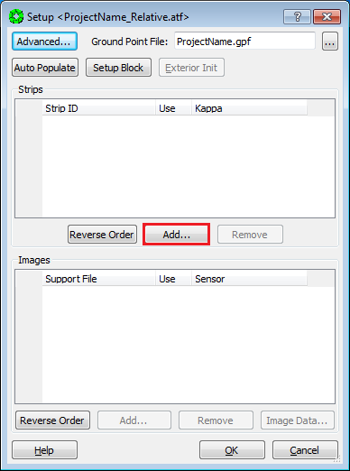
Note that in the Setup Window, the Ground Point File: (to be created) will automatically be named after the project name.
-
In the Strip ID Sequence box, use the default value of 1, and press
OK.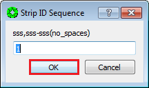
-
You will be prompted to Select Support Files. Do this by highlighting each image in the
Availablelist and moving them toSelectedlist via the arrow buttons. PressOKwhen done.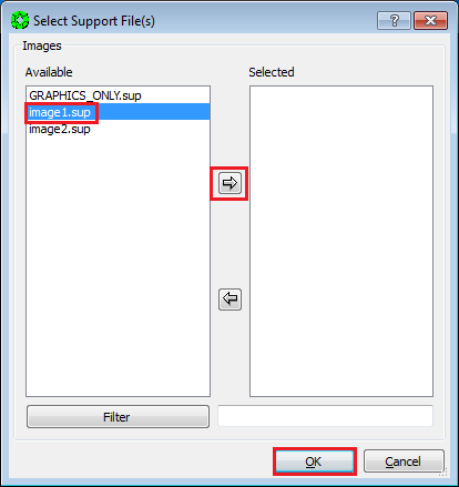
-
The selected images are now listed in the Setup window. Select the nadir-most image, and press
Image Data….
-
In the Image Data window:
a. make sure no check boxes are checked in the Adjust field.
b. Turn on radio button
Selected Image(s) Onlyin theApply Tosection.c. Press “OK”.
Note:
- Not allowing any parameters to adjust holds this image to it’s a-priori position and pointing.
- Please ignore the values listed in the Accuracy field, as they may not be applicable to the setup in certain cases

-
Go back to the Setup window. Select the Support file of the other image, and press
Image Data….
-
In the Image Data window:
a. Turn on the check boxes for the parameters listed below, and enter the corresponding accuracy values. (All other parameters are off. If a parameter is checked, it will be allowed to adjust. If it is not checked, it will remain unchanged when the triangulation is run.)
b. Turn on radio button
Selected Image(s) Onlyin theApply Tosection.c. Press
OK.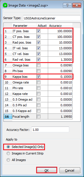
Parameter Accuracy IT pos. bias 100 m CT pos. bias 100 m Radial pos. bias 10 m IT vel. bias 13 m/s CT vel. bias 13 m/s Radial vel. bias 1.3 m/s Kappa bias 0.1 degree -
Press
OKin the Setup window.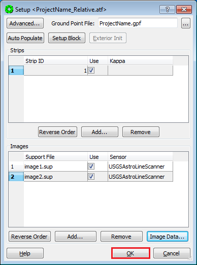
-
Select
File > Save Triangulation Filein the Automated Triangulation window.
Using Interactive Point Measurement (details below), we will measure two “tie points” per region, as distributed in 8 regions shown here, for a minimum of 16 points. This point distribution is called “Buddy Points”, and aids in highlighting poor image measurements when solving a bundle adjustment.
NOTE: We want to convert as many of these tie-points to z-only control in the Vertical Adjustment to MOLA stage, so when possible avoid steep slopes areas.
- Ensure that the
View 1window in the stereo display is set for stereo mode. - Be seated squarely in front of the stereo display (with stereo viewing glasses).
- Press
Interactive Point Measurementfrom the Automated Triangulation window.
- Press
Settingsin the Interactive Point Measurement (IPM) window.
- In the Settings for IPM window, check the
Auto Img Listbox, then press “Close”.
-
In the IPM window:
a. Right Click in the Point ID field.
b. Select “Add” in the pop-up window.

-
On the TopoMouse, use the zoom out button (repeatedly), to view full extents of the stereo model.

-
Move cursor to first (or next) region for tie point measurement.

-
Use TopoMouse “Zoom in” button (repeatedly) to set view to approximately 8:1 ratio.

-
Locate an area where terrain is relatively continuous with minimal slope, and move extraction cursor to that location.

-
In the IPM window, lock the Left image by checking its Lock box.

-
Clear parallax by moving the Right image only and place the extraction cursor on the ground. You may use the Z wheel to fine-tune the height adjustment of the extraction cursor after Y-parallax is removed.

Note: You need to practice the placement of the cursor on the ground several times, until you have clear sense of when it is above or below the ground. See Appendix: A-3 Placing Dot on the Ground.
-
Use the TopoMouse “Zoom In” button (repeatedly) to set view to 1:1 ratio.

-
In the IPM window, Unlock the Left image by unchecking its Lock box.

-
Refine the extraction cursor position to a highly discernible location that is representative of surrounding terrain and free of high relief or slope. Do not measure edges of shadows, because shadows “move” between image scenes, and the extraction cursor will not be truly on the ground.

-
In the IPM window, lock the Left image by checking its Lock box.

-
Refine the parallax removal (at ground level) by moving the Right image only. In other words, put the dot on the ground.
Note: Experienced analysts with good stereo acuity to recognize when auto-correlation has correlated to a false positive result, may want to use the “Auto-Two” feature in this step. For details, see Appendix: A6.1 Auto Two Feature in IPM.
-
Press
Sampleon the IPM window to collect the point measurement.Note: Sample stores the measurement in computer memory only. After Sample is pressed, both images will be locked and measured.

-
Press
Saveon the IPM window to write the measurement to disk.
-
Start measurement of second (buddy) point in the same region:
a. In the IPM window, Right Click in the Point ID field.
b. Select
Addin the pop-up window.
-
Move the extraction cursor to a new location in the current field of view.
-
In the IPM window, lock the Left image by checking its Lock box.

-
Refine the parallax removal (at ground level) by moving the Right image only. In other words, put the dot on the ground.
Note: Experienced analysts with good stereo acuity to recognize when auto-correlation has correlated to a false positive result, may want to use the “Auto-Two” feature in this step. For details, see Appendix: A6.1 Auto Two Feature in IPM.
-
Press
Sampleon the IPM window to measure the (buddy) point.
-
Press
Saveon the IPM window to write the measurement to disk.
-
Go To: Step 1 of this section (17.4 Manual Tie Point Measurement), and repeat this procedure for each of the regions defined in 17.2 Tie Point Distribution.
-
After completing the measurement process for all 8 regions (16 points), press
Closeon the IPM window.
-
Return to the Automated Triangulation / Full Block menu in the MST, and activate the adjustment procedure by pressing
Solve.
-
The
Simultaneous Solvewindow will open, along with aBackuppop-up window. PressYeson the pop-up to overwrite back up files.
-
In the
Simultaneous Solvewindow, pressStartto perform the bundle adjustment.
-
Once the adjustment is completed, the
Simultaneous Solvewindow will be updated with a report of: Number of ground points generated, solution redundancy, and most importantly the RMS residual error (in Image pixels).An acceptable solution has (1) an Image (pixels) RMS of ~0.6 or less, and (2) no individual point measurement has an error greater than 2 pixels.
Press “Results” in the “Simultaneous Solve” window to review the error of individual point measurements.

-
Points in the Residuals window are grouped by Type, and automatically sorted from highest to lowest residual. The Line and Sample fields list the point measurement errors in pixels. In a Relative Orientation, all points are Tie, so inspecting the top of the list will suffice.

-
If points have pixel errors greater than 2.0 pixels, SKIP TO: 17.6 Point Re-Measurement Process. Otherwise, continue to the next step.
-
If the image RMS is < ~0.6 pixels, and the maximum point measurement error is < 2.0 pixels, then press “Close” on the Multi-Sensor Triangulation Residuals window.

-
Press
Saveon the simultaneous solve window.
-
Press
Yeson the Done pop-up window.
-
Press
Closeon the Simultaneous Solve window.
-
Select
File > Exiton the Automatic Triangulation window.
Relative Orientation is now complete!
-
SKIP: 17.6 Point Re-Measurement Process, GO TO: 17.7 Re-Load Images.
Continuing from 17.5 Bundle Adjustment…
-
On the
Multi-Sensor Triangulation Residualswindow, Left-Click on the Point ID(s) of the points to re-measure. (Hold the Control Key down to select multiple points.) Then pressRe-measure Point(s)…. The re-measure point window will now open with the points selected.
-
Left-Click on the point to re-measure. The View 1 (stereo display) will display the current point measurement.

-
You have an option of relocating the point or clearing parallax:
a. To relocate the point, Un-check the boxes in the
Measuredfield for both images.b. To remove residual parallax, Un-check the Measured box for the Right image only.
NOTE: Un-checking a Measured box will also un-Lock the image so it is free to move using the TopoMouse.

-
If you are re-locating the point, place the extraction cursor on the feature in the Left image that you would like to measure. Then Lock the Left image by checking the box in the Lock field for the Left image.

-
For either option (re-locating the point, or removing residual parallax), clear the parallax by moving the Right image only (i.e., put the dot on the ground).
-
Press
Sampleto collect the point measurement.
-
Press
Saveto write the measurement to disk.
-
Repeat re-measurement process for remaining points in the list. (Go back to step 2.)
-
Press
Closeafter all points in the list are re-measured.
-
Press
Closeon the Multi-Sensor Triangulation Residuals window.
-
Press
Starton the Simultaneous Solve window.
-
Press
Residualson the Simultaneous Solve window and make sure no individual point has an error greater than 2 pixels.
-
If there are points with larger than 2 pixel errors, Go To: Step 1 of this section (17.6 Point Re-Measurement Process) and further refine the measurements.
-
If the overall RMS < ~0.6 pixels, and all points have less than a 2 pixel error, we will exit Multi-Sensor Triangulation, and re-enter it in order to refresh the values stored in computer memory. First press
Closeon the Multi-Sensor Triangulation Residuals window.
-
Press
Closeon the Simultaneous Solve window. (Do Not PressSave.)
-
Press
Noto Saving Files in the Done pop-up window.
-
Select
File > Exiton the Automatic Triangulation window.
-
From the SOCET SET menu bar, select
Preparation > Multi-Sensor Triangulation.
-
Press
Solveon the Automatic Triangulation window. (The triangulation file, ProjectName_Relative, should load automatically.)
-
Press
Yeson the pop-up to overwrite back up files.
-
Press
Starton the Simultaneous Solve window.
-
If the Image (pixels) RMS is < ~0.6 pixels, Press
Saveon the Simultaneous Solve window.
-
Press
Yeson the Done pop-up window.
-
Press
Closeon the Simultaneous Solve window.
-
Select
File > Exiton the Automatic Triangulation window.
Relative Orientation is now complete!
After the Relative Orientation is complete, it is necessary to re-Load the images in order to view them with the results of the adjustment. You should now have a parallax-free stereo model.
-
From the SOCET SET menu bar, select
File > Load Images.
-
In the Image Loader window, select the Left and Right Image to display by clicking on the image id in the Left and Right panels. (Selected images will be highlighted.)

-
Under
View Control Panelsettings: Ensure thatView = 1and thatLoad Pointis selected.
-
Press
Load.
-
Press
Close”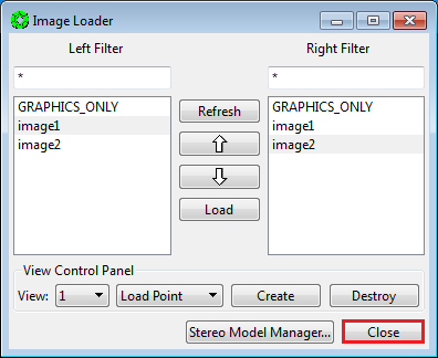
##Backup Relative Orientation Results
At this point, it is prudent for the operator to backup the project data in order to have a re-entry point that does not require the re-measure of tie points.
-
From the SOCET SET menu bar, select
USGS Tools > Backup Orientation.
-
Make sure the current project name is listed in the Project field. If not, press “Project” to select the current project, then press “OK”. (Otherwise the backup will be made in, and for, the wrong project!)


-
Replace
Backup_0with_Relativein the Local folder name field. The backup folder will be named<ProjectName>_Relative.
-
Press
Backup.
