Output Nodes
This node measures the value of a qubit ('0' or '1') and saves the result on a classical bit.
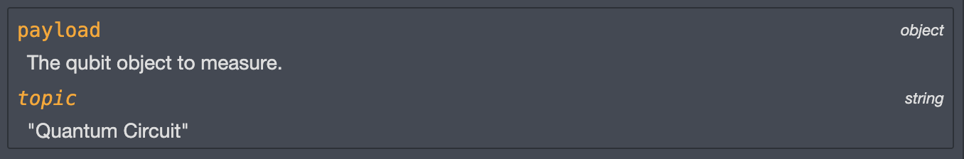
To do so, open the node properties and select on which classical bit to save the measurement result:
- If using registers, select a classical bit from the appropriate classical register.
- If not using registers, select a classical bit from the list.
Since we measure and interpret a qubit state using classical machines, this can be seen as a projection of quantum computing back to classical computing: from quantum states back to binary values.
This leads to probabilistic measurement results. In terms of the Bloch Sphere, the closest the qubit state is from the '1 state', the more likely we are to measure a '1'.
Careful - The act of measuring a qubit collapses the qubit state: the state of the qubit after being measured is not representative of the qubit state before the measurement.
Please measure the qubits at the end of the quantum circuit or reset them after a measurement.
Qubit measurement - Qiskit textbook
Qubit measurement - Qiskit documentation
This node is used to generate a bloch sphere representation of the state of each qubit.
To do so, place this node at the end of the quantum circuit and
connect all qubit objects from the circuit.
If not all qubit objects are connected, the node will assume that
the circuit has not finished running and will wait indefinitely.
To visualise the generated bloch spheres into the Node-RED editor, we recommend to download the
node-red-contrib-image-output
module and connect it to the output of the Bloch Sphere node.
Careful - Measure nodes are not compatible with the Bloch Sphere node because
the act of measuring a qubit collapses the qubit state.
Please remove Measure nodes from the circuit before using the Bloch Sphere node.
For more details on the Bloch Sphere representation of qubit states, please refer to the
Details section of the Quantum Circuit node.

Bloch Sphere - Qiskit textbook
Bloch Sphere - Qiskit documentation
This node is used to generate a diagram of your quantum circuit.
To do so, place this node at the end of the quantum circuit and
connect all qubit objects from the circuit.
If not all qubit objects are connected, the node will assume that
the circuit has not finished running and will wait indefinitely.
To visualise the generated diagram into the Node-RED editor, we recommend to download the
node-red-contrib-image-output
module and connect it to the output of the Circuit Diagram node.
It is a common feature in Qiskit to generate visual representations of your circuit for
debugging since it is often easier to visualise a quantum circuit rather than reading the equivalent python code.
Circuit Diagram - Qiskit documentation
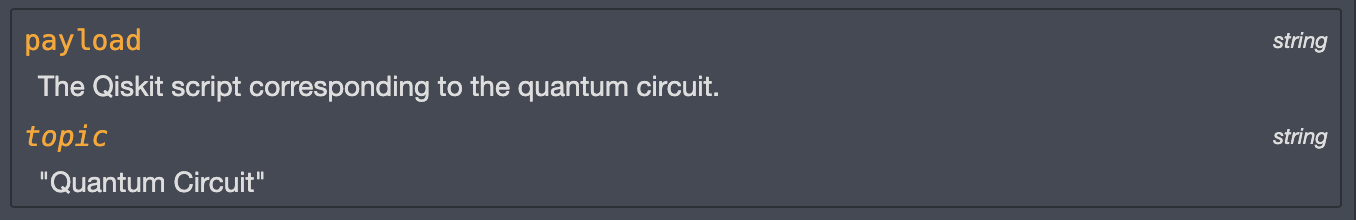
This node is used to generate the python Qiskit script of the quantum circuit.
To do so, place this node at the end of the quantum circuit and
connect all qubit objects from the circuit.
If not all qubit objects are connected, the node will assume that
the circuit has not finished running and will wait indefinitely.

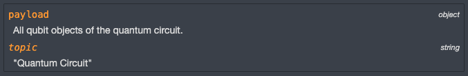
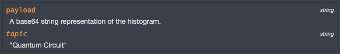
This node simulates the operation of the quantum circuit and returns a histogram representation of the outputs.
To do so, indicate the number of times you would like to simulate the circuit (shots),
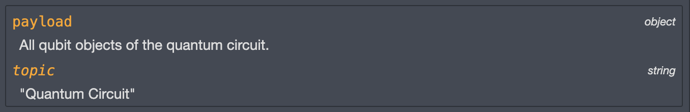
place this node at the end of the quantum circuit and
connect all qubit objects from the circuit.
If not all qubit objects are connected, the node will assume that
the circuit has not finished running and will wait indefinitely.
To visualise the generated diagram into the Node-RED editor, we recommend to download the
node-red-contrib-image-output
module and connect it to the output of the Circuit Diagram node.
The output of a quantum circuit correspond to the value of the classical bits that were set up with the circuit.
The Measure node is the only node capable of changing a classical bit value. Simulating a quantum circuit
without any Measure nodes will simply result in all the shots generating the same number: the default classical
bits value (e.g. 000 for 3 bits).
The number of shots refers to the number of times the circuit is run to obtain
a probability distribution of results. This is due to the probabilistic nature of qubit measurements.
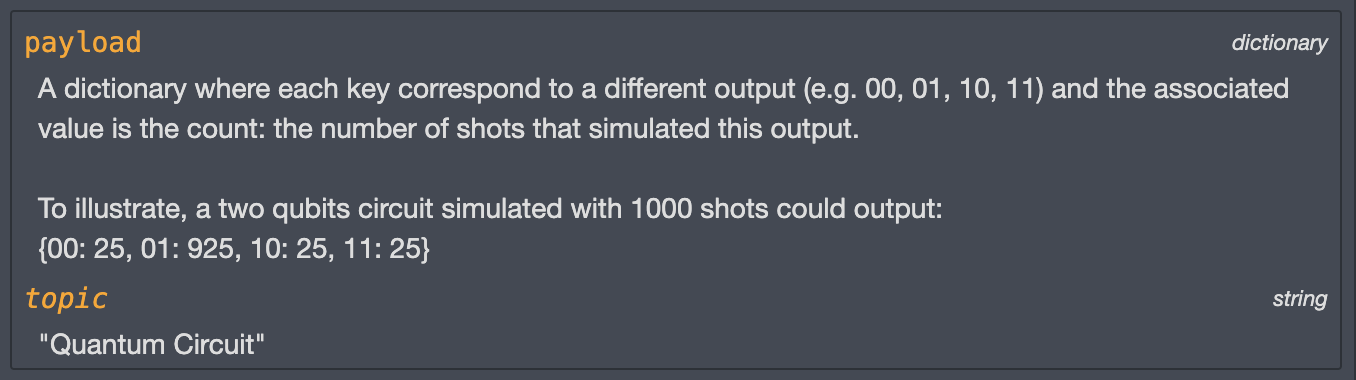
The 'counts' refer to the number of shots that resulted in each output of the circuit.
For more information about qubit measurements, please refer to the Measure node documentation.
This node makes use of Qiskit's local QASM simulator.
QASM simulator - Qiskit documentation
Counts output - Qiskit documentation
Histogram - Qiskit documentation
This node simulates the operation of a quantum circuit and returns a simulated output.
To do so, indicate the number of times you would like to simulate the circuit (shots),
place this node at the end of the quantum circuit and
connect all qubit objects.
If not all qubit objects are connected, the node will assume that
the circuit has not finished running and will wait indefinitely.
The output of a quantum circuit correspond to the value of the classical bits that were set up with the circuit.
The Measure node is the only node capable of changing a classical bit value. Simulating a quantum circuit
without any Measure nodes will simply result in all the shots generating the same number: the default classical
bits value (e.g. 000 for 3 bits).
The number of shots refers to the number of times the circuit is run to obtain
a probability distribution of results. This is due to the probabilistic nature of qubit measurements.
The 'counts' refer to the number of shots that resulted in each output of the circuit.
For more information about qubit measurements, please refer to the Measure node documentation.
This node makes use of Qiskit's local QASM simulator.
QASM simulator - Qiskit documentation
Counts output - Qiskit documentation
This node sends the quantum circuit to be run on an actual quantum system and outputs the results.
The quantum backends are provided by IBM Quantum Services.
This node requires an internet connection.
1 -
First, you need to open an IBMid account (free) and use it to
sign in with IBM Quantum. From the dashboard,
you will be able to copy your API token and paste it into the node's properties.
2 -
Then, you can either choose to run your circuit on:
- The least busy remote IBM quantum simulator
- The least busy actual IBM quantum system
If you want to use a specific quantum backend from IBM, you can indicate its name in the 'Specific Quantum Backend' input field (e.g. 'ibmq_lima'). If empty, the node will use the least busy backend with enough qubits to run your circuit.
You can find a list of quantum backends in your IBM Quantum account.
Please be aware that because of cloud services availability, your circuit will be put in a queue, waiting to be executed on an IBM backend which can take some time. You can check your job status from your IBM Quantum account.
3 - Indicate the number of times you would like to simulate the circuit (shots).
4 - By default, this node only returns the results (counts) of the quantum circuit. However, you can select the 'Verbose' output option to include more information such as the quantum machine it was run on, the job ID, the time it took to run etc.
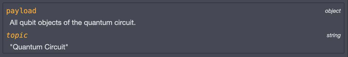
5 - Finally, place this node at the end of the quantum circuit and connect all qubit objects.
If not all qubit objects are connected, the node will assume that the circuit has not finished running and will wait indefinitely.
The output of a quantum circuit correspond to the value of the classical bits that were set up with the circuit.
The Measure node is the only node capable of changing a classical bit value. Simulating a quantum circuit without any Measure nodes will simply result in all the shots generating the same number: the default classical bits value (e.g. 000 for 3 bits).
The number of shots refers to the number of times the circuit is run to obtain a probability distribution of results. This is due to the probabilistic nature of qubit measurements.
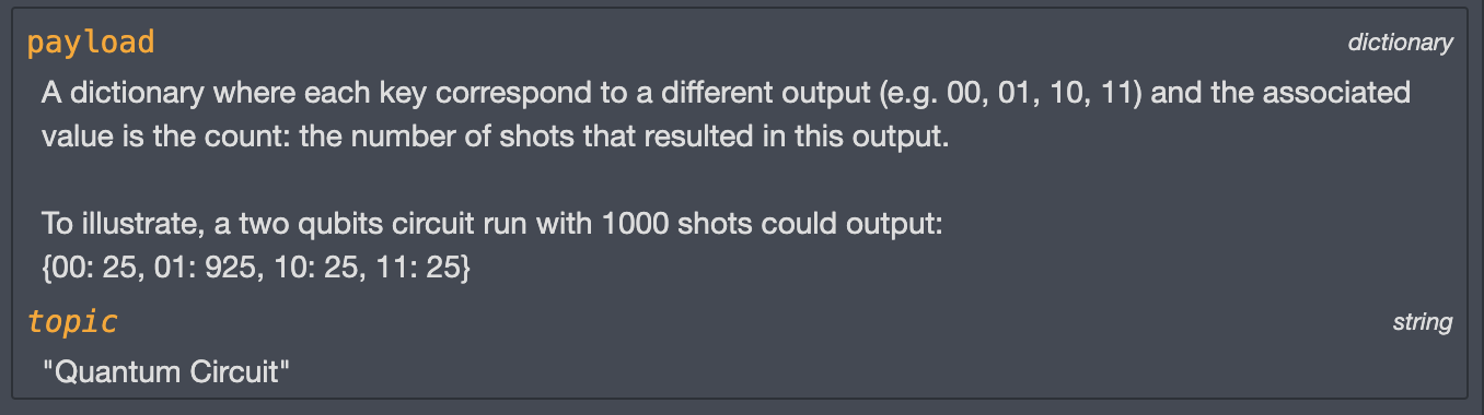
The 'counts' refer to the number of shots that resulted in each output of the circuit.
For more information about qubit measurements, please refer to the Measure node documentation.
s
About IBM Quantum Systems
Counts output - Qiskit documentation