Block Diagrams and Data Flow
These diagrams give a high-level overview of the architecture of our software and hardware, followed by detailed pictures of the data flow within our system.
Our hardware is relatively simple, as the only components directly connected to the vision system are the main controller and the RealSense camera. It is organized as follows:
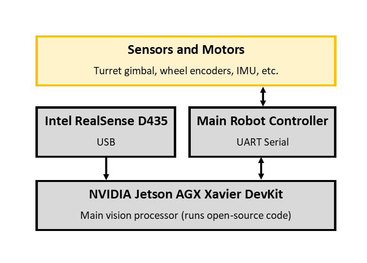
The Jetson Xavier gets visual and depth input from the RealSense, to do plate detection and localization. The main controller sends it movement odometry and turret angle feedback, and in return the Jetson sends back desired aim angles.
Software is slightly more complex; the data connections, organized into blocks by major code module, are illustrated below.
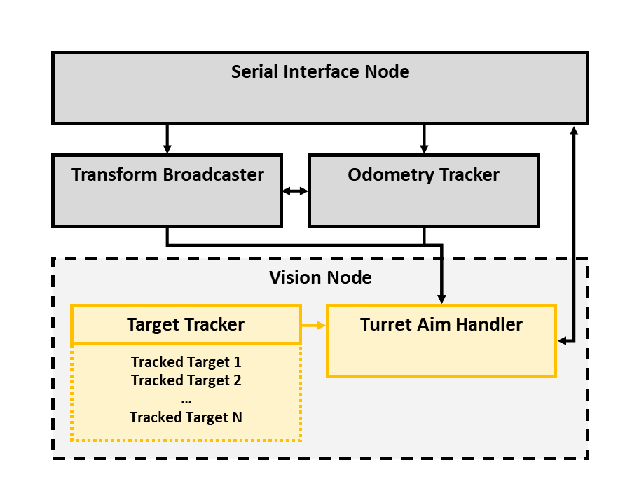
The transform broadcaster is responsible for publishing data on how the robot is physically laid out. In addition to static transforms such as the relationship between the turret axis and the camera mounting on the turret, it also broadcasts dynamic transforms in response to sensor data from the serial node, such as the relationship between the robot chassis and the turret axis.
The serial node does no processing other than acting as a relay between the serial line and the ROS topics our other nodes use. When messages arrive via serial, it parses them and publishes an appropriate message via ROS. When messages are published within the ROS ecosystem on a topic intended to be relayed out, it serializes the message and sends it via serial. The protocol is documented here.
The odometry node is responsible for fusing wheel movement data and IMU data, along with past measurements, and publishing true odometry which specifies the robot's location and velocity in 3D space relative to an arbitrary starting point. For the theory behind this operation, see our page on Kalman Filters.
Finally, the vision node does the bulk of our vision processing. Individual TrackedTargets keep track of data about individual plate targets we've recently seen. The TargetTracker takes input from our armor plate detection network and correlates new frame detections with past detections, passing relevant data to its TrackedTargets. (More theory on the tracking is available here.) The AimTurret class facilitates turning detections into turret aim commands, by doing motion-corrected ballistics calculations.
Our application is comprised of four main "nodes", which talk to each other via ROS "topics". The node topology is shown in the diagram below.
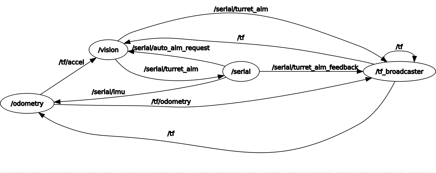
These nodes are connected by many independent topics, some of which are only used as configuration from outside sources and don't actually connect two distinct nodes. The topic connections are illustrated below. Not shown is the camera input, taken directly into the vision node via the USB video device, and the serial output produced by the serial node
