-
Notifications
You must be signed in to change notification settings - Fork 1
Pulse Width Modulation
Pulse width modulation is a very common control method in digital systems. It is most widely used by servo motors.
As you might guess, pulse width modulation transmits information via a pulse's whose width is modulated (or changed).
In other words, the frequency of data transmission is constant. The only thing that changes is how long the signal is high versus low.
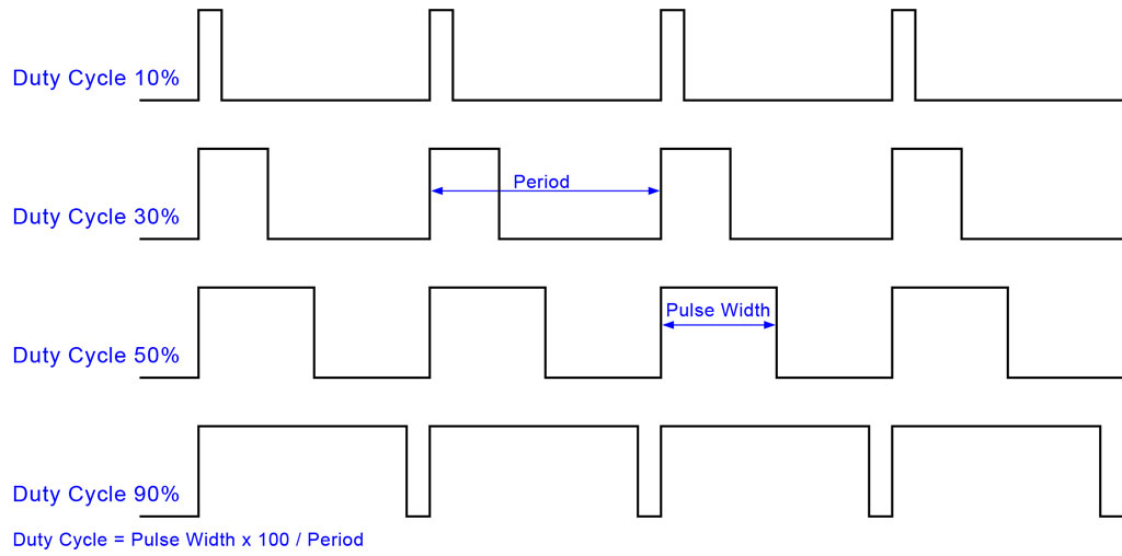
This controlling of how long a signal is high or low is known as the duty cycle of a signal.
For example, a standard digital signal that spends half its time high and half its time low has a duty cycle of 50% because it spends 50% of its time high.
If the signal spent 70% of its time high and 30% of its time low, then the duty cycle would be 70%.
The duty cycle is the important part of PWM because it tells the receiver what to do! For example, sending a signal with a 50% duty cycle might tell a servo to seek its center point while a 0% duty cycle might tell it to rotate 180 degrees on way and 100% duty cycle would tell it to rotate 180 degrees the other way. Of course, real servos have all sorts of different requirements. First, you need to figure out what frequency of signal the receiver is expecting. Then, once you have that, you can convert it into a delay (the period of the signal). The next step is finding the range of duty cycle. This is where you'll find the greatest variety among motors. Some specify the duty cycle of each position while others specify a delay in us (microseconds). Either way, it will be easiest to convert to a duty cycle percentage when implementing it. This is because you implement PWM quite easily by the following:
- Set the signal high
- Delay for the duty cycle percent of the total signal period For example, a 50% duty cycle would be: 0.5 * T (where T is the period)
- Set the signal to low
- Delay for 1 - the duty cycle So for the 50% duty cycle: (1 - 0.5) * T (where T is the period)
Here is an image example of what a PWM signal would look like:
